The moment a red-hot aluminum profile exits the extrusion press and enters the quench tank, its final shape hangs in the balance. Some profiles emerge perfectly straight. Others twist, bow, or warp beyond salvage. The difference often comes down to one question: what shape will distort after quenching?
For production managers and process engineers, this is not an academic question. It is a daily battle against scrap rates, rework costs, and missed delivery deadlines. Understanding which geometries are vulnerable—and why—is the first step toward consistent quality.
This guide provides a systematic framework for predicting quenching distortion based on profile shape. More importantly, it offers practical solutions for preventing warpage at the source, whether through process optimization or equipment upgrade.
The Hidden Cost of Quenching Distortion
Quenching distortion does not just create scrap. It generates cascading costs throughout your operation. Every bent profile requires manual straightening, consuming labor hours that could be spent on value-added work. Every twisted section that escapes detection leads to customer complaints and potential returns.
Industry data suggests that quenching-related distortion accounts for 3-8% of total production scrap in typical extrusion plants. For a facility producing 10,000 tons annually, this represents 300 to 800 tons of wasted material. At current aluminum prices, that is hundreds of thousands of dollars in lost revenue.
Beyond direct material costs, distortion creates production bottlenecks. Manual straightening stations become the slowest point in the line. Rework queues grow. Delivery dates slip. The hidden cost of distortion is not just what you throw away—it is the throughput you never achieve.
The good news is that most quenching distortion is predictable. And predictable problems are preventable.
The Metallurgical Why: What Happens During Quenching
Before examining specific shapes, we must understand the underlying mechanism. Quenching is fundamentally about locking the alloy’s strengthening elements in solid solution. The profile is heated to solution temperature (typically 500-550°C for 6xxx series alloys), then rapidly cooled to prevent premature precipitation.
The challenge is that cooling never happens uniformly across a complex cross-section. Thin sections cool faster than thick sections. Surfaces exposed directly to the quenchant cool faster than recessed areas. These temperature gradients create differential contraction rates within the same profile.
Aluminum’s physical properties compound this challenge. Its coefficient of thermal expansion is roughly twice that of steel—2.38×10⁻⁵ mm/mm compared to 1.12×10⁻⁵ mm/mm. This means a 100°C temperature difference across a profile generates significantly more internal stress than in ferrous materials.
As Dr. D. Scott MacKenzie notes in his work on aluminum heat treatment, “Aluminum is more prone to quenching distortion than steel. This is because solution heat-treating temperatures are so close to the liquidus temperature. Aluminum exhibits less strength and greater plasticity at the solution heat-treating temperature.”
When these internal stresses exceed the material’s yield strength at elevated temperatures, permanent deformation occurs. The profile warps. The shape distorts. And you are left with a bin full of rejects.
Profile Geometry Matters: Which Shapes Are at Risk
Not all aluminum extrusions are created equal when it comes to quenching distortion. Certain geometries are inherently more vulnerable. Understanding these risk categories helps focus preventive efforts where they matter most.
Category 1: Asymmetric Sections
L-shaped, T-shaped, and other non-symmetrical profiles are prime candidates for twisting. The center of mass does not align with the geometric center. During quenching, one leg cools faster than the other, creating a torsional moment that literally twists the profile along its length.
Typical distortion pattern: Helical twisting, often increasing toward the trailing end of the profile.
Risk level: High. These sections rarely survive quenching without some degree of twist unless carefully controlled.
Category 2: Thin-Walled Hollow Sections
Square and rectangular tubes with wall thicknesses below 2mm face a different challenge. Their high surface-area-to-volume ratio means they cool extremely rapidly. Too rapidly. The sudden temperature drop can cause localized buckling, particularly on flat faces.
Typical distortion pattern: Concave face depression (“oil-canning”), overall bowing, or both.
Risk level: Moderate to High. Success depends heavily on quenchant selection and flow control.
Category 3: Solid Thick Sections
Chunky profiles with minimal surface area relative to mass seem like they should be safe. They are not. The problem here is differential cooling between surface and core. While the surface quenches rapidly, the interior remains hot for seconds longer. This creates massive residual stress that may not manifest as immediate distortion but will cause warpage during subsequent machining or aging.
Typical distortion pattern: Delayed warpage during post-processing. The profile may appear straight off the line but curl after the first machining pass.
Risk level: Moderate. The distortion is hidden until later stages, making it particularly insidious.
Category 4: Multi-Cavity Complex Sections
Profiles with multiple internal voids—common in thermal break window designs or automotive structural components—present the ultimate quenching challenge. Each cavity cools at a different rate. Each web and rib contracts independently. The result is a complex internal stress field that often manifests as overall bowing or twisting.
Typical distortion pattern: Combined bow and twist, often varying unpredictably along the length.
Risk level: Very High. These profiles require the most sophisticated quenching control.
Diagnosis Checklist: Is It the Shape, the Process, or the Equipment?
When faced with persistent distortion, the natural instinct is to blame the shape itself. Sometimes that is correct. Often, however, the shape is merely exposing limitations in your process or equipment.
Use this three-level diagnostic checklist to pinpoint the true root cause.
Level 1: Shape Factors
- Does your profile fall into one of the high-risk categories above?
- Is the distortion pattern consistent with the shape’s predicted behavior?
- Have you successfully run similar shapes before with different results?
If the shape is clearly the primary variable, you need geometry-specific solutions. If similar shapes have run successfully, look deeper.
Level 2: Process Factors
- What is your quench transfer time? (The gap between die exit and quench entry should be under 15 seconds for most 6xxx alloys.)
- What quenchant are you using? Water, polymer, or air-mist?
- What is your quenchant temperature? (Cold water increases quench rate but also distortion risk.)
- Are your settings optimized for this specific alloy and temper requirement?
Process adjustments can often mitigate shape-related distortion without capital investment.
Level 3: Equipment Factors
- Does your quenching system provide uniform cooling across the entire profile cross-section?
- Can you independently control cooling intensity on different sides of the profile?
- Does your system maintain consistent performance across the full length of the profile?
- Can you store and recall optimized parameters for different profile geometries?
If your equipment cannot deliver the precision required for your most challenging shapes, process tweaks will only get you so far.
A simple rule of thumb: if you have optimized your process for a given shape and still see distortion, the equipment is the limiting factor.
Beyond Diagnosis: Engineering Solutions for Shape-Specific Distortion
Once you have identified the root cause, targeted solutions become possible.
For Asymmetric Sections
The goal is to balance cooling rates across the unequal legs. This may mean directing additional quenchant flow to the thicker section, or shielding the thinner section to slow its cooling. In extreme cases, consider redesigning the extrusion to incorporate balancing features—small ribs or mass additions that equalize section thickness.
For Thin-Walled Hollows
The priority here is quenching intensity control. Water quenching is almost always too aggressive for thin walls. Air-mist or polymer quenchants provide the necessary cooling rate with reduced thermal shock. Some producers successfully use staged quenching—initial air cooling followed by gentler liquid quench—to achieve the right balance.
For Solid Thick Sections
The challenge is internal stress, not immediate distortion. Solution heat treatment parameters matter enormously here. Longer solution times at slightly lower temperatures can reduce thermal gradients during quenching. Subsequent stretching (1-3% permanent deformation) is essential to relieve the locked-in stresses before aging or machining.
For Multi-Cavity Complex Sections
These profiles demand the most sophisticated approach. Individual control of cooling intensity for different cavities—through strategically positioned nozzles or adjustable flow dividers—offers the best chance of success. This is where equipment capability becomes the deciding factor.
When process optimization reaches its limits, the conversation inevitably turns to equipment. Can your current quenching system deliver the profile-specific control these shapes require?
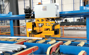
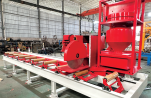
How Pinrui’s Adaptive Quenching System Addresses Shape-Specific Distortion
Pinrui Machinery has spent over a decade engineering solutions for the industry’s most challenging profiles. Our online quenching systems are designed from the ground up to address the geometry-specific distortion mechanisms described above.
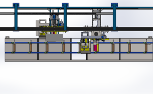
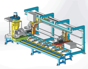
Multi-Zone Independent Control
Standard quenching systems apply the same cooling intensity everywhere. Pinrui’s modular hood design divides the quenching zone into independently controlled segments. Each segment can deliver air, water mist, or a combination, at pressures and flow rates tailored to that specific section of the profile.
For an asymmetric L-shape, this means directing higher cooling intensity to the thick leg while moderating flow to the thin leg. The temperature gradient across the profile collapses. The twisting moment never develops.
PLC Recipe Management
Every profile is different. Pinrui’s PLC-based control system stores complete quenching recipes for each of your products. When a 6063 thin-walled tube runs, the system automatically recalls the optimized air-mist settings that worked last time. When a 6061 solid bar follows, it switches to the appropriate water flow parameters.
This is not theoretical. Customers routinely report that recipe-based control reduces setup time from hours to minutes and eliminates the trial-and-error that wastes material and production time.
Real-Time Feedback and Adjustment
Static recipes are good. Dynamic adjustment is better. Pinrui systems can incorporate temperature sensors that monitor the profile during quenching. If actual cooling deviates from the target curve, the system adjusts flow rates in real time to compensate.
This closed-loop control is particularly valuable for multi-cavity complex sections where theoretical cooling models rarely match reality. The system learns. It adapts. It delivers consistent results across production runs.
Backed by 24 patents and deployed in over 30 countries, Pinrui’s quenching technology represents a fundamental advance in distortion control. We do not just cool profiles. We engineer the thermal path that preserves their intended shape.
Real-World Results: From Distortion to Dimensional Stability
Case Study 1: Asymmetric Section for Solar Mounting
A Chinese solar frame extruder struggled with twisted L-shaped sections. Twist rates averaged 4-6%, requiring full-time manual straightening. After installing a Pinrui online quenching system with multi-zone control, twist rates dropped below 1.2%. Manual straightening was eliminated entirely.
Case Study 2: Thin-Walled Tube for Automotive Heat Exchangers
An automotive supplier could not achieve consistent straightness on 1.5mm wall tubes quenched in a traditional water bath. The switch to Pinrui’s precision air-mist system reduced bow from 3mm/m to under 0.8mm/m, meeting customer specifications for the first time.
Case Study 3: Multi-Cavity Window Profile
A European-style thermal break profile consistently warped during quenching, forcing the manufacturer to scrap 8% of production. Pinrui’s cavity-specific cooling control—using individually tuned nozzles for each internal void—brought scrap below 1% and enabled the company to accept orders they previously had to refuse.
These are not isolated successes. They represent a pattern: when shape-specific quenching challenges meet engineered solutions, distortion yields to dimensional stability.
Frequently Asked Questions About Quenching Distortion
Q1: Can quenching distortion be completely eliminated?
For most profiles, distortion can be reduced to within commercial tolerance limits. Complete elimination—perfect straightness on every piece—is theoretically possible but practically uneconomic for standard production. The goal is predictable, repeatable straightness that meets customer requirements without secondary operations.
Q2: How do I know if my quenching system is causing distortion?
Run a controlled test with a known “good” profile. If the same profile distorts when run on your line but not on a reference line, your equipment is the variable. Temperature logging across the profile during quenching can also reveal non-uniform cooling patterns that point to equipment limitations.
Q3: What’s the difference between water quenching and air-mist quenching for thin profiles?
Water quenching removes heat at rates exceeding 100°C/second. Air-mist typically operates in the 20-50°C/second range. For thin-walled profiles, the slower rate reduces thermal shock while still achieving required mechanical properties for most 6xxx alloys. The trade-off is lower throughput, as profiles must spend more time in the quench zone.
Q4: Does profile length affect distortion risk?
Yes, for two reasons. Longer profiles have more time to accumulate differential cooling effects. They also sag more between support points on the cooling bed, introducing gravitational bending that compounds quenching distortion. For lengths above 6 meters, cooling bed design becomes as important as quenching control.
Q5: Can I retrofit my existing line to handle complex shapes better?
Often, yes. Pinrui offers modular quenching upgrades that integrate with existing extrusion lines. The key is whether your current cooling bed and handling equipment can maintain profile stability after the upgraded quench. A full line audit can identify the optimal upgrade path.
Next Steps: Diagnose Your Distortion Problem
You now understand which shapes are most vulnerable to quenching distortion and why. You have a framework for diagnosing whether shape, process, or equipment is the root cause. You have seen how targeted solutions—including Pinrui’s adaptive quenching systems—transform distortion-prone profiles into consistent, salable products.
The next step is applying this knowledge to your specific situation.
For immediate action: Download our comprehensive Quenching Distortion Diagnostic Checklist. This expanded version includes detailed questions for each risk category, data collection templates, and comparison charts to benchmark your current performance.
For deeper analysis: Submit a profile drawing and your current distortion data. Our engineers will provide a confidential assessment of your quenching challenges and recommend targeted solutions—whether process adjustments or equipment upgrades.
For serious evaluation: Schedule a remote line audit with a Pinrui applications engineer. We will review your current operation, identify bottlenecks, and deliver a preliminary proposal for achieving the dimensional consistency your most demanding customers require.
The profiles that distort today do not have to define your production tomorrow. With the right diagnosis and the right equipment, even the most challenging shapes can emerge from quenching straight, stable, and ready for the next operation.